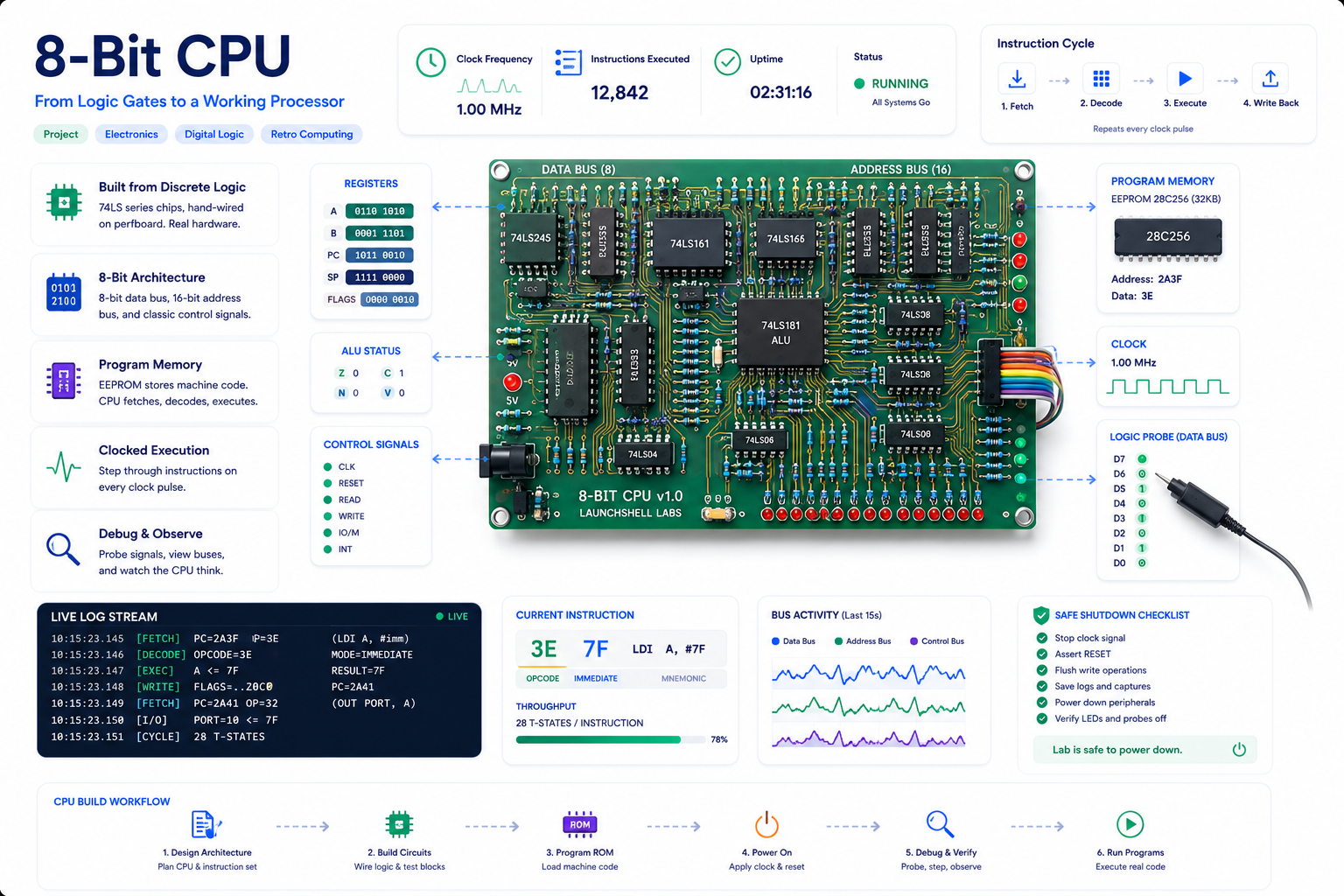
This project connects software to real hardware: a from-scratch 8-bit CPU on a custom PCB,
plus Python tools that turn a tiny assembly language into EEPROM contents.
The point is not just to simulate a CPU. The point is to write instructions, generate ROM images,
burn them into real chips, move the EEPROM to the board, and watch the hardware execute.
A hardware/software project for learning CPU architecture, buses, registers, microcode, ROMs, and the real
path from source code to electrical behavior.
What this project is
This is a custom educational CPU project. The design starts from the classic Ben Eater-style 8-bit computer,
then moves toward a single-PCB build with Python-generated ROM images and an Arduino-based EEPROM programmer.
Project Goal
Build the computer and the toolchain
The CPU is only half the project. The other half is the software pipeline that lets me write simple
assembly,
encode it into bytes, generate a ROM image, and program an EEPROM that the hardware can actually run.
This project sits between computer science, electrical engineering, and embedded systems.
CPU Architecture
Datapath and control
Registers, buses, ALU behavior, flags, instruction fetch, program counter movement, and how control signals
make the datapath do work.
Digital Logic
Real chips, real timing
Glue logic, tri-state buses, latches, edge-triggered registers, clock sequencing, control lines, decoupling,
and electrical debugging.
Tooling
Assembler and ROM generation
A small Python toolchain parses assembly, encodes instructions, creates a byte listing, and outputs data
suitable for EEPROM programming.
Python → Arduino → EEPROM workflow
The workflow is intentionally practical. I want to change code, regenerate bytes, burn the ROM, and test it on
the board.
01
Write assembly
Edit a tiny source file like program.asm.
02
Assemble it
Run the Python assembler to turn mnemonics and operands into bytes.
03
Send bytes
Send the generated ROM image over serial to the Arduino Nano.
04
Program EEPROM
The Nano drives shift registers, address lines, data lines, and write control.
05
Run on hardware
Move the EEPROM to the CPU board and observe the output register or LEDs.
Instruction set starting point
The ISA is intentionally small. The goal is to make each instruction easy to understand and easy to trace
through the hardware.
Mnemonic
Meaning
LDA
Load accumulator from memory.
ADD
Add memory value to accumulator.
SUB
Subtract memory value from accumulator.
STA
Store accumulator to memory.
LDI
Load an immediate value into the accumulator.
JMP
Jump to another address.
JC
Jump if the carry flag is set.
JZ
Jump if the zero flag is set.
OUT
Copy the accumulator to the output register.
HLT
Halt the CPU.
Tiny sample program
This is the kind of tiny assembly program the Python tooling is meant to parse and encode.
; Example: load a value, store it, read it back, and output
LDI 0x0
STA 0xF
LDA 0xF
OUT
HLT
Microcode idea
The control unit is microcoded. Each instruction runs as a sequence of smaller control steps.
Control ROM
Opcode + step + flags → control word
The control word is a bitfield. Each bit drives something on the CPU: register load lines,
output enable lines, ALU operation selection, memory read/write, program counter increment/load,
and the output register.
Long term, the same Python tooling can generate not only instruction ROM images, but also the microcode ROM
image.
(opcode, microstep, flags)
          ↓
      control_word
          ↓
Register load / enable
ALU operation select
Memory read / write
Program counter control
Output register enable
EEPROM programmer
To avoid manually entering bytes, I built a simple ROM loader around an Arduino Nano.
What it writes
AT28C64 EEPROM
The programmer writes bytes to specific EEPROM addresses and can read them back for verification.
How it expands I/O
74HC595 shift registers
The Nano does not have enough GPIO for everything, so shift registers fan out address, data, and control
signals.
Why it matters
Fast experiment loop
Once the programmer works, I can change the assembler or microcode and burn new EEPROM contents quickly.
Current status
This project is still active. The point of the page is to show the build honestly: completed work, testing work,
and next steps.
Done
Completed so far
CPU schematic and PCB routed in KiCad.
Required components sourced and received.
Switched to 28C64 EEPROMs with unused address lines tied low for now.
EEPROM loader proof of concept completed on breadboard.
Basic Python assembler and ROM generator started.
Next
Work in progress
PCB assembly and bring-up: power rails, clock, reset, continuity, and first tests.
Initial ISA experiments with small test programs.
Control word format and microcode ROM generation.
Cleaner Arduino Nano EEPROM programmer in C.
More documentation: photos, block diagrams, and build notes.
Why this belongs on LaunchShell
This is exactly the kind of project LaunchShell is meant to document: a real build that connects theory,
tools, mistakes, debugging, and practical systems thinking.
01
Build it
Design the CPU, route the PCB, source parts, assemble the board, and build the ROM loader.
02
Back it up
Keep KiCad files, assembler code, ROM images, notes, and test programs in version control.
03
Break it
Expect wiring issues, timing problems, bad assumptions, incorrect control bits, and failed test programs.
04
Learn why
Use the failure points to understand how real machines execute instructions at the signal level.
Related resources
These are useful starting points for readers who want to understand the background.
Inspiration
Ben Eater 8-bit computer
The original educational breadboard computer series that inspired the starting architecture.
This project is a bridge between code and hardware. Python generates the bytes, an Arduino writes them to ROM,
and the CPU board turns those bytes into visible behavior. That makes every layer observable: source code,
opcodes, memory addresses, control signals, and physical output.